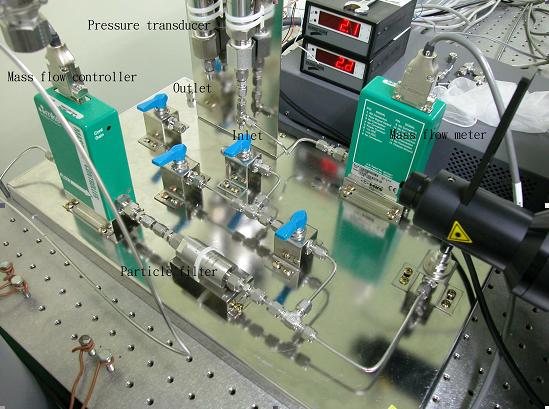
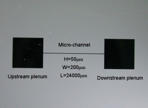
A typical micro-channel is shown in Fig. 1. Fig. 2 is a photograph of the present test loop Nitrogen (N2) gas was supplied and controlled from a pressurized cylinder with a regulator, and flowed through a mass flow meter (MKS Instruments Inc.), two particle filters (one is 0.5μm and one is 0.003μm), passed two pressure transducers and two thermistors through the test section at inlet pressure of up to 3.45 bavp. The test section outlet was connected to a mass flow meter (MKS Instruments Inc.) having a flow rate range of 0.005 to 0.19 mg/s for the present flow rate measurements.
| Fig.1 | Fig.2 |
 |
 |